Getting some height
Post 4
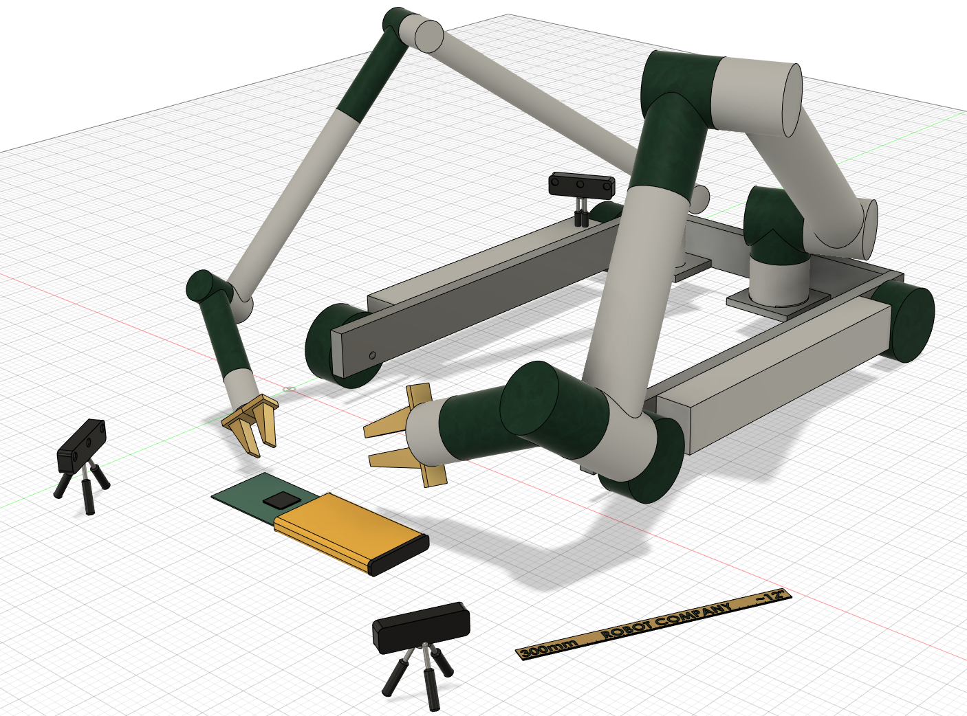
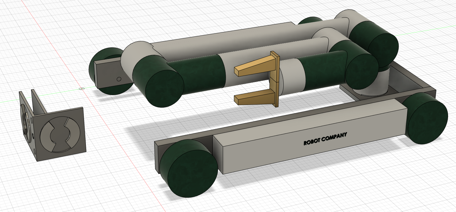
Previously, we had a lobster robot that rolled around on the ground.
It had two arms.
It still has two arms.
I just didn’t draw the small arm this time.
It's not the focus of the topic at hand.
Just get a desk job.
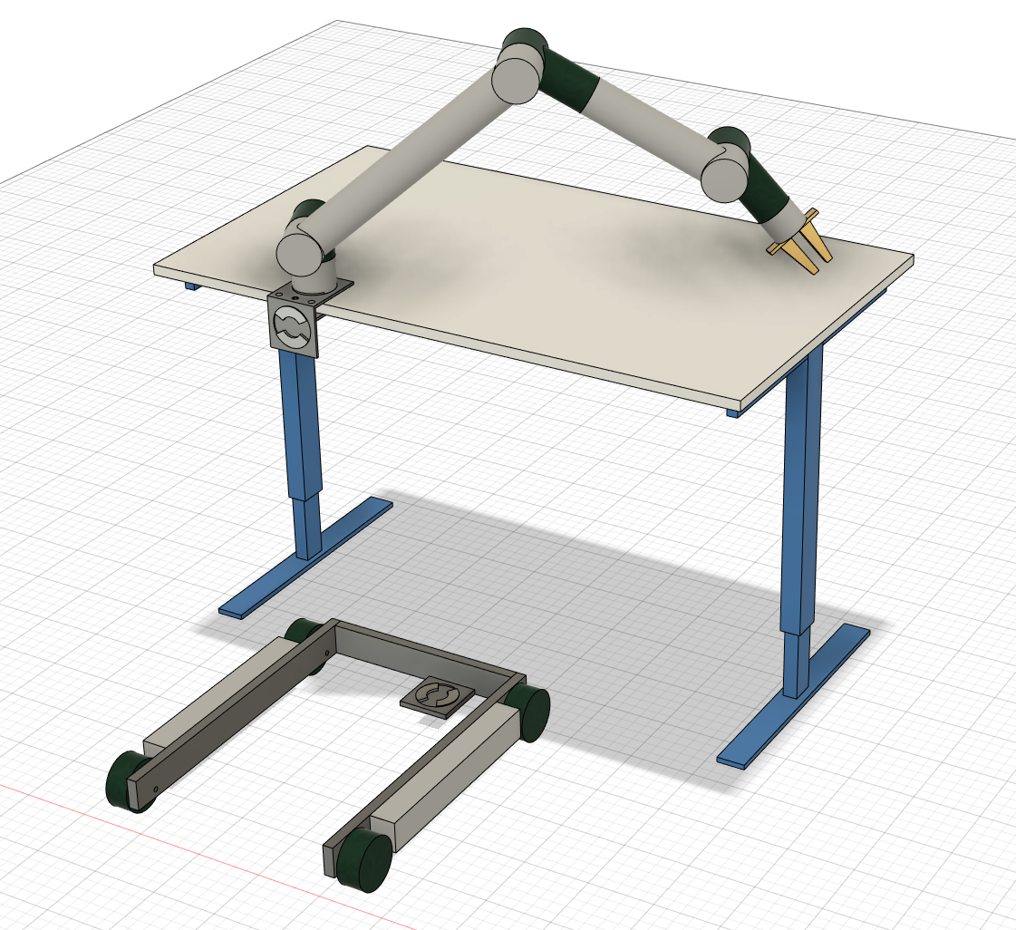
So, the idea is to make a way for the arms to get up onto tables. This is in order to be more useful in a wider range of light industry tasks.
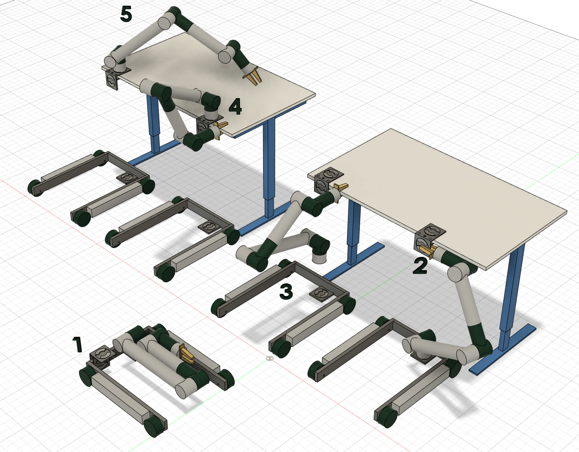
And if the picture isn't clear enough,
- the robot carries around an extra clamp device. Maybe on its shoulder, maybe somewhere else.
- It then mounts the clamp (somehow) onto a surface.
- Then it grabs the surface and disconnects itself from the base
- It then places itself up on the clamp.
- From here it has a good position to access the local desk area.
After this, the other arm (not shown) would also find it's way onto the surface to help out.
When the task is complete, they climb back down and move onto the next job.
At which point we all need to deal with about 12 months of influencers predicting the end of the world for everyone with a desk job.
But, before that… let’s start with the pressing issues.
Issues
Weight and grip
Robot arms are generally quite heavy. There might even be no prior cases of a working solution to have an arm try and lift its own body (too bold a statement).
There are now smallish actuators that can lift pretty heavy things, but it's still an assumption that they would be practical in this case.
The gripper trying to grab the table is also a bit of a red flag. A lot can go wrong regarding different surfaces. It would make more sense that the gripper connects (somehow) with the clamp itself. Then the clamp takes full responsibility for the surfaces that it is designed for. This allows several clamps to be designed for specific surfaces, rather than trying to work a general solution into the design of the gripper.
This would also allow the arm to test the clamp for a stable connection before using it. Maybe it just grabs it and pulls on it or something.
Cables and hardware drivers
It's not really decided how the power will go.
It's likely that batteries and extra power connections will stay in the base. The motor driving electronics might also be kept there.
That means some cable management from the base up to the arm on the desk. That will be a challenge.
Software, sensors, control, etc.
Yes, well. One does not simply assume this is easy.
But, it is all too tempting to put a little black box on the robot with “AI” written on it. 🤦♀️
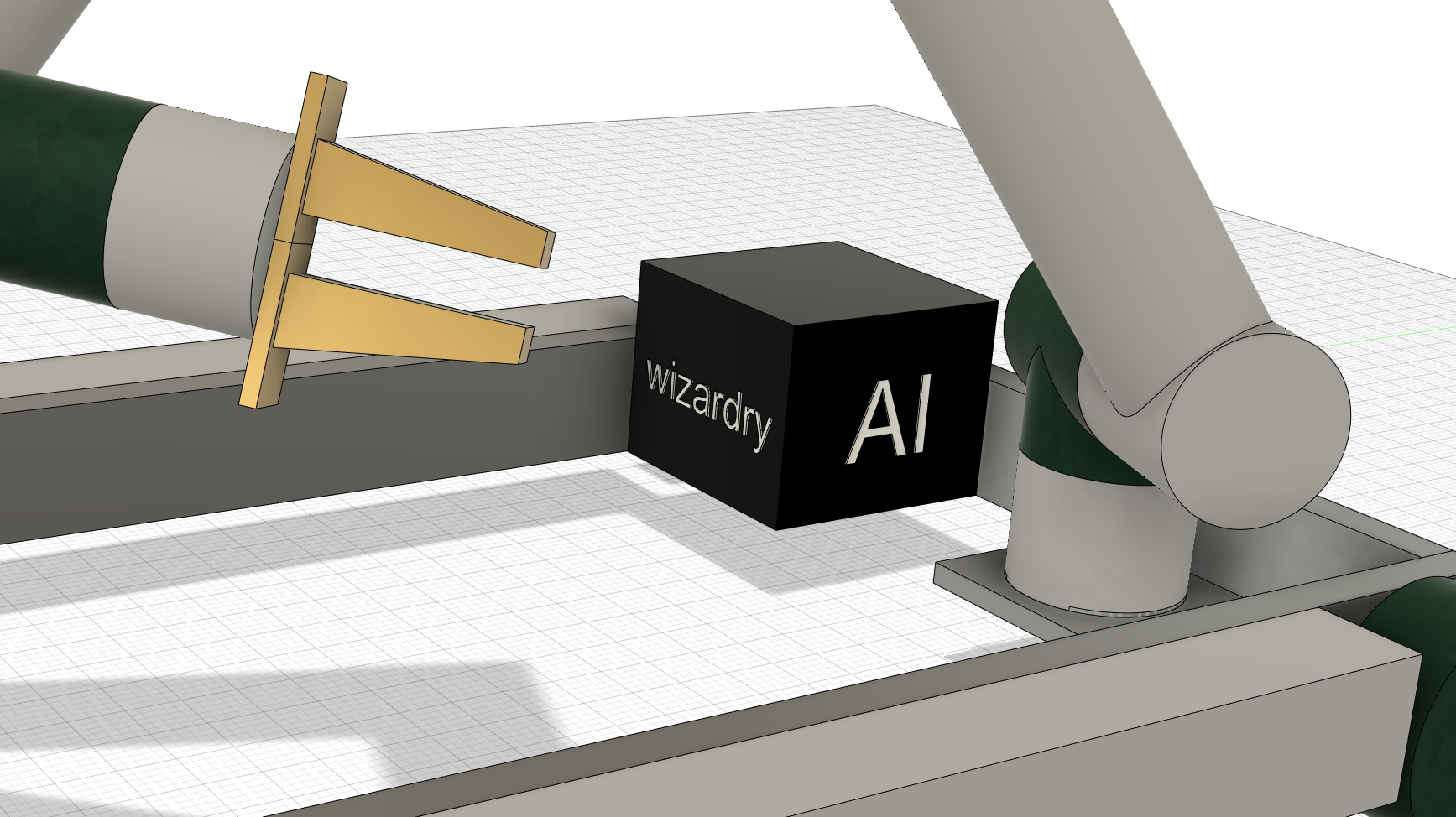
Yes, there will be some elements that people call AI today, but nothing that says:
🚩 Hopelfully this new technology will scale in the near future in order to make our business model viable. Invest in us today! 🚩
This is not how this is going to work. A future link to the user story will go <here>.
Progress Sketches
Here’s some working material.
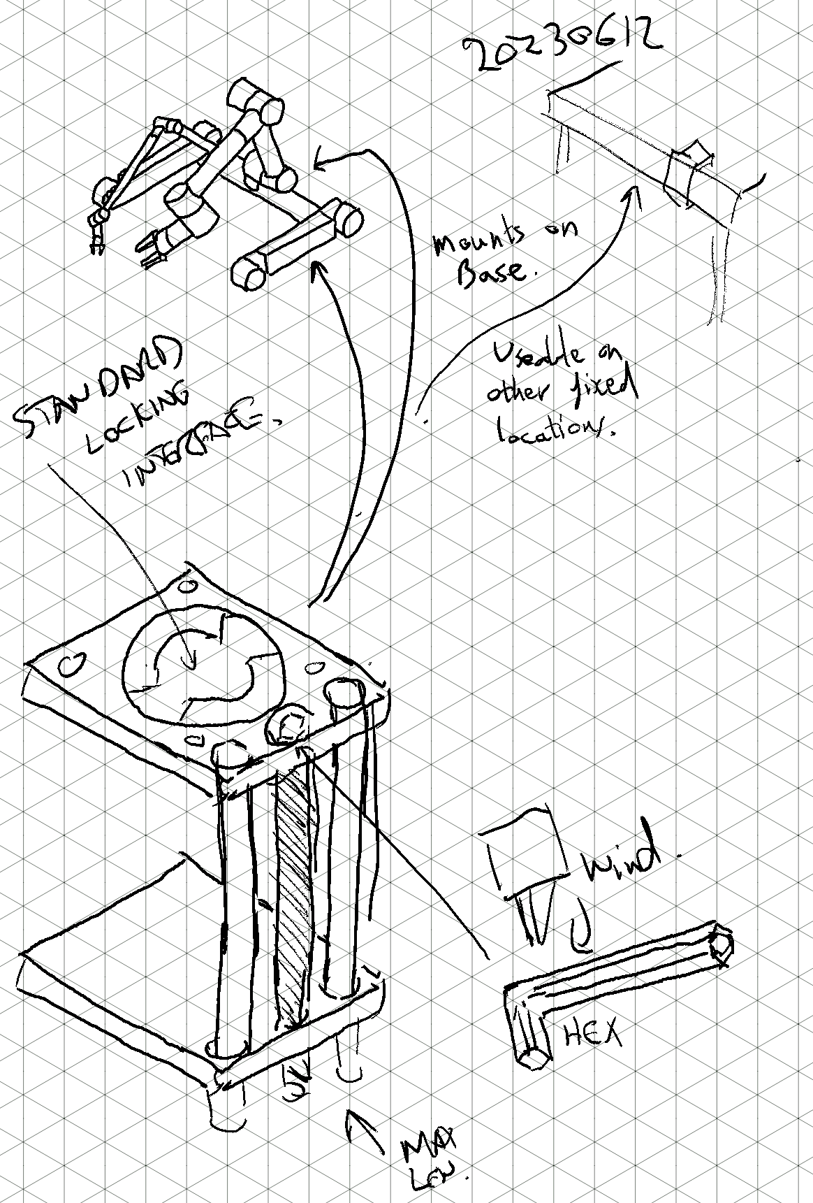
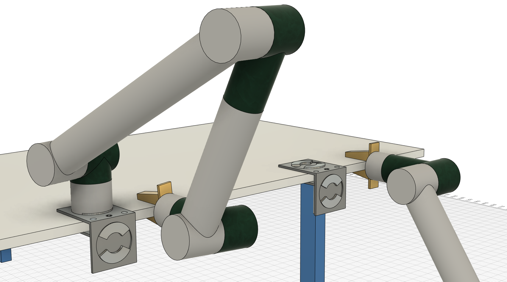
Locking interface
The arm and clamp would have some kind of … locking interface.
Perhaps this could be activated by the help of the other arm.
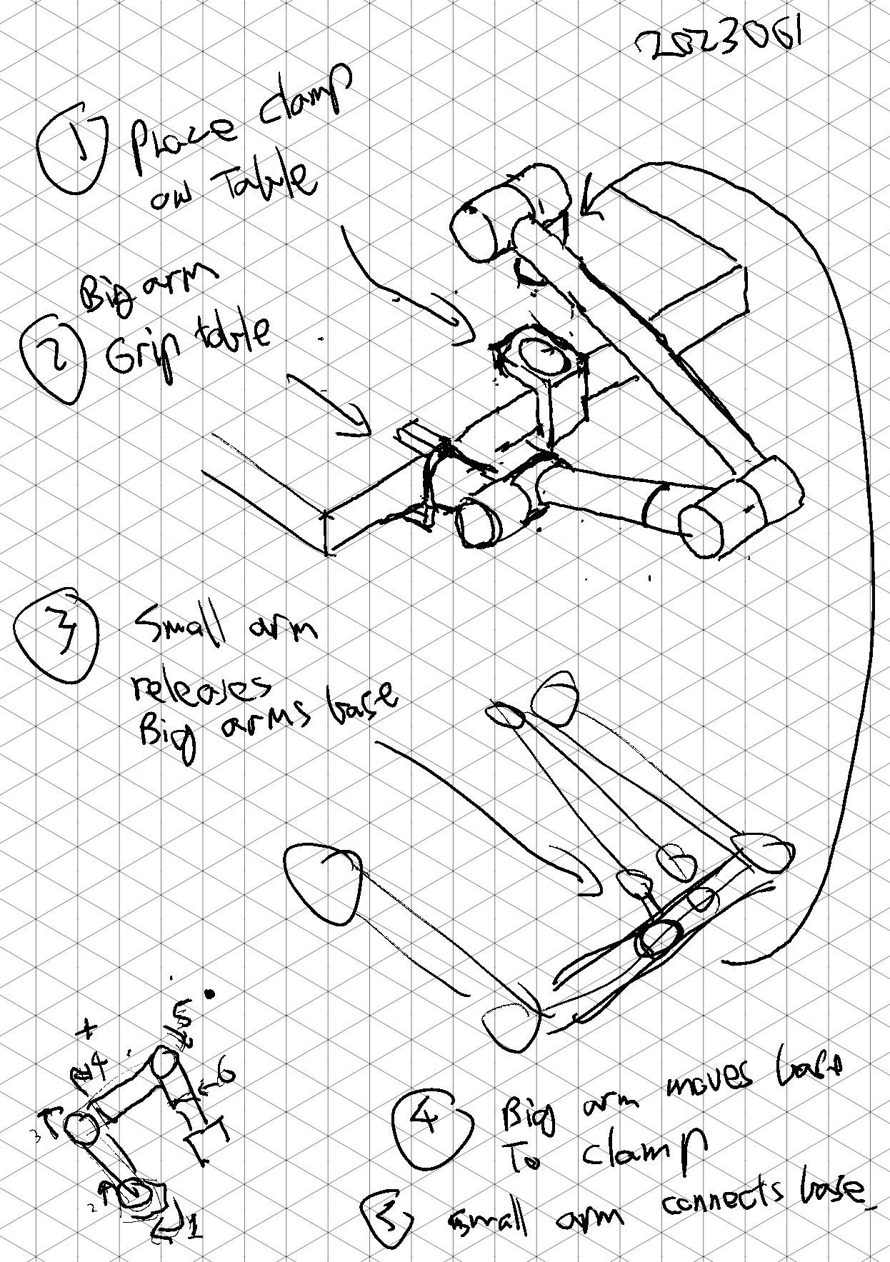
Here is some sketches that kind of show the behaviour.
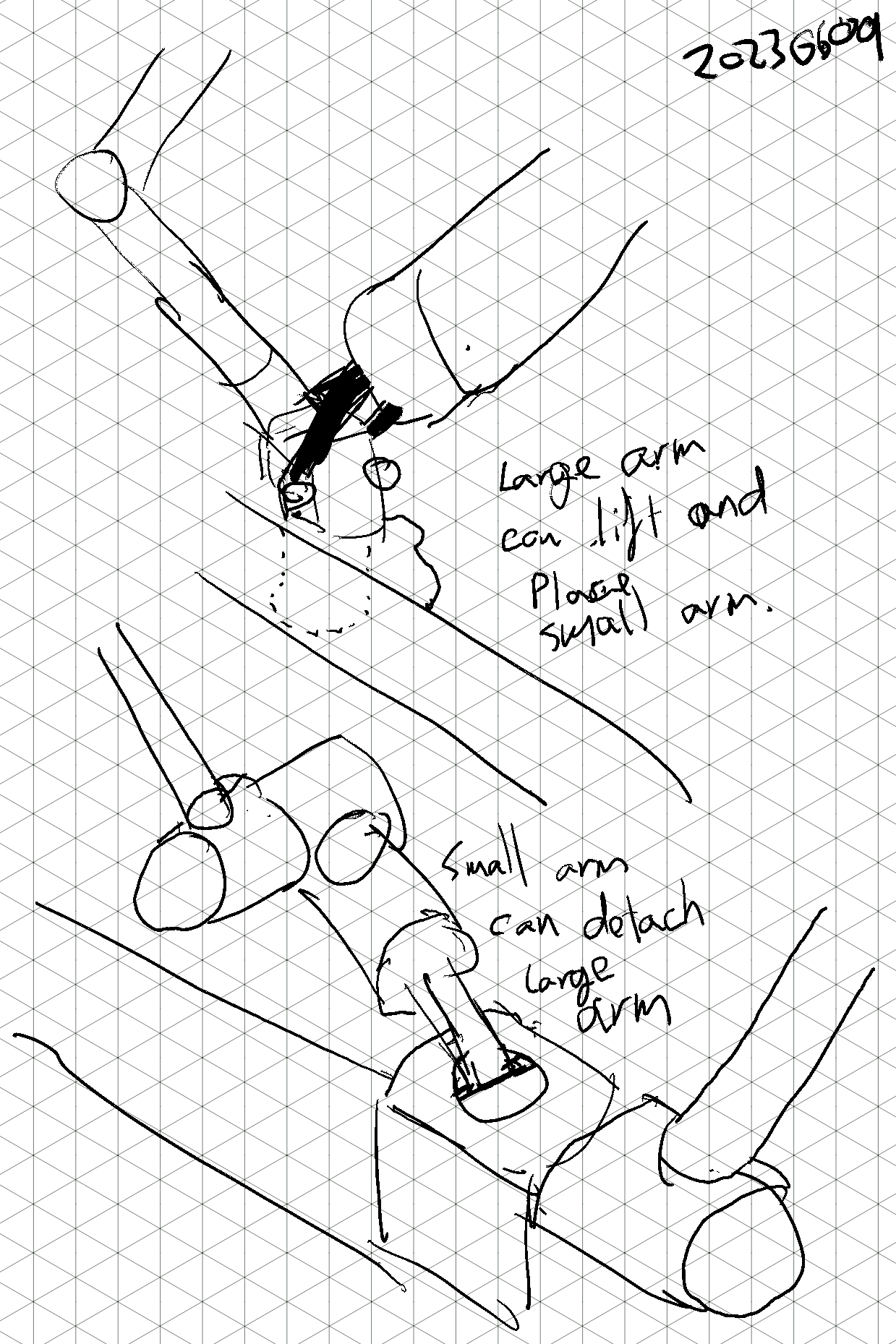
The big arm can perhaps carry the small arm by its base to a new position.
The small arm might only help the big arm by locking/unlocking it from the base.
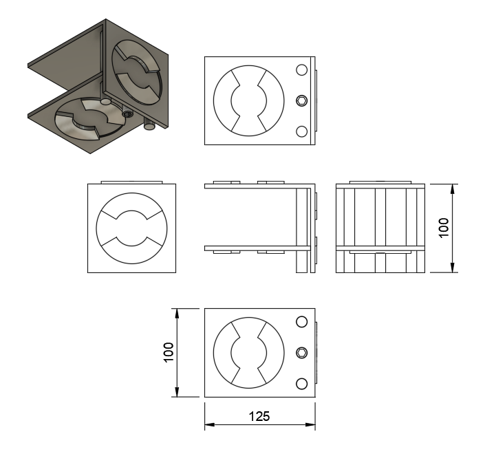
Concept CAD
What size clamp dimensions?
How will the locking interface work?
The way to make a good clamp and locking interface is to contract someone with experience.
Before that, it needs to be determined if the concept is practical at all.
This drawing serves purely as a communication tool.
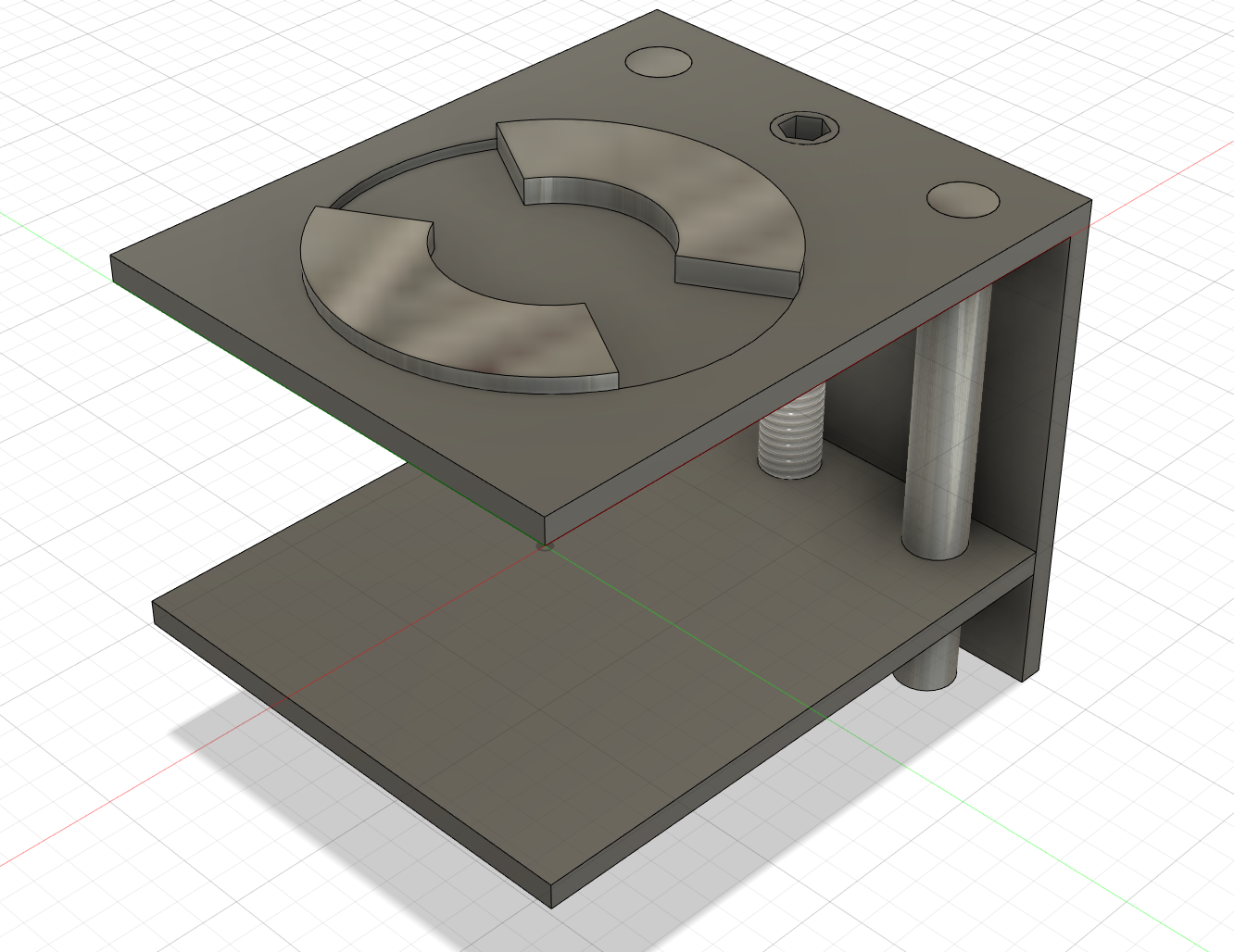
It's just a simple clamp with a locking mechanism on several sides to make it easy to play around with.
Re-dimensioning
At this point, there is minimal value in getting the size exactly right.
However, I still did some basic resizing of the for this work (based on last post on size). Regarding “easy storage”, it's not clear if this is important at all. Upcoming work on the business model suggests the robot may never really be stored at all.
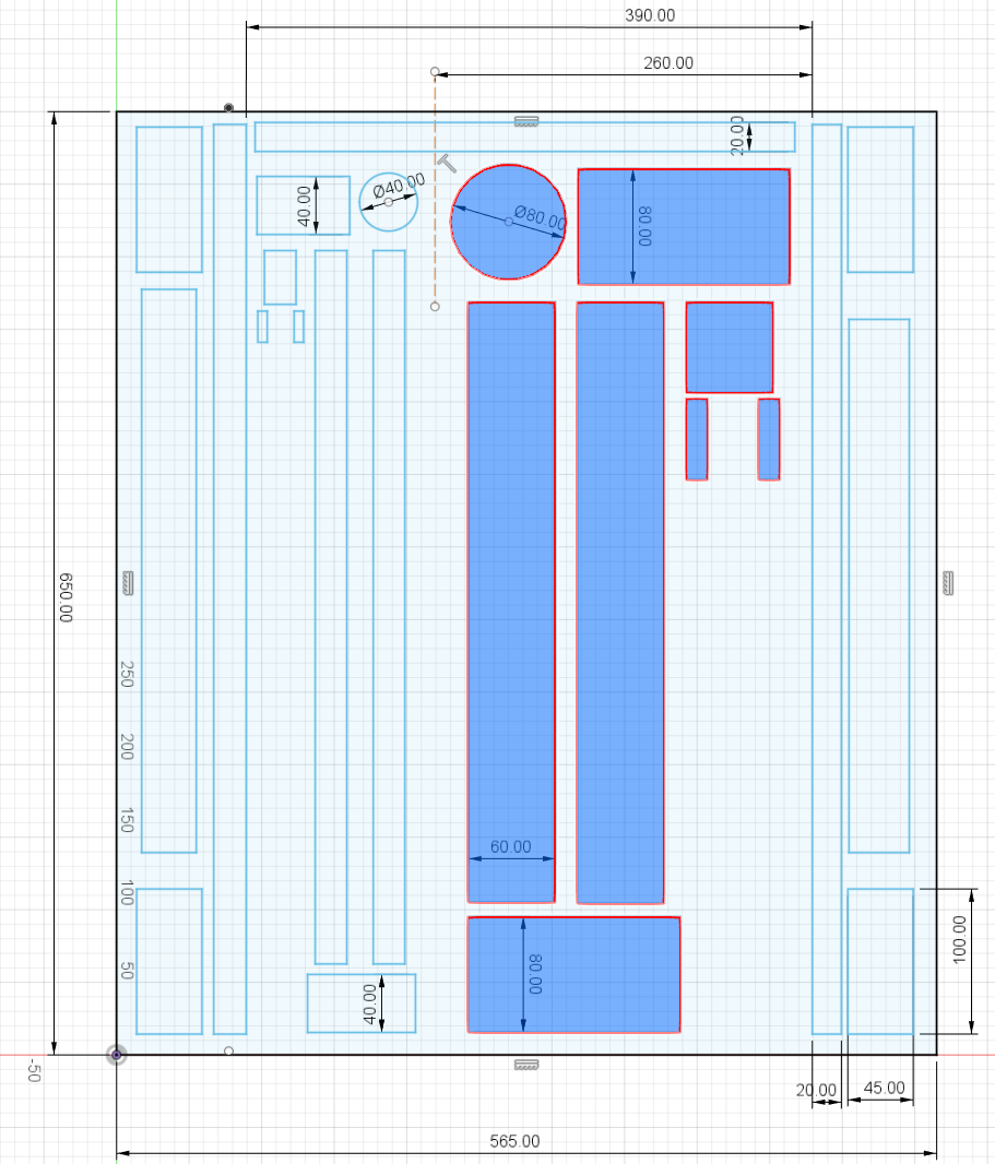
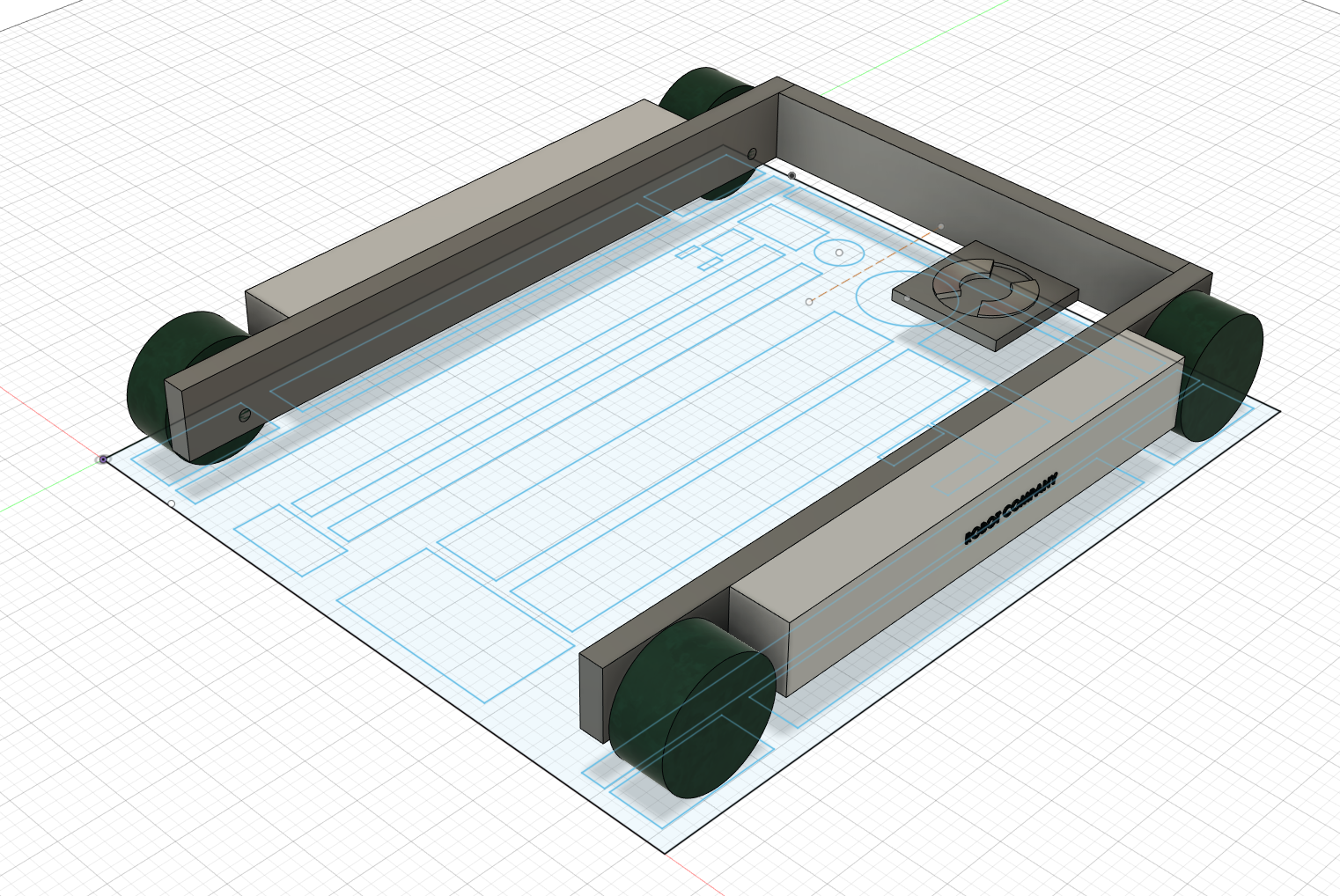
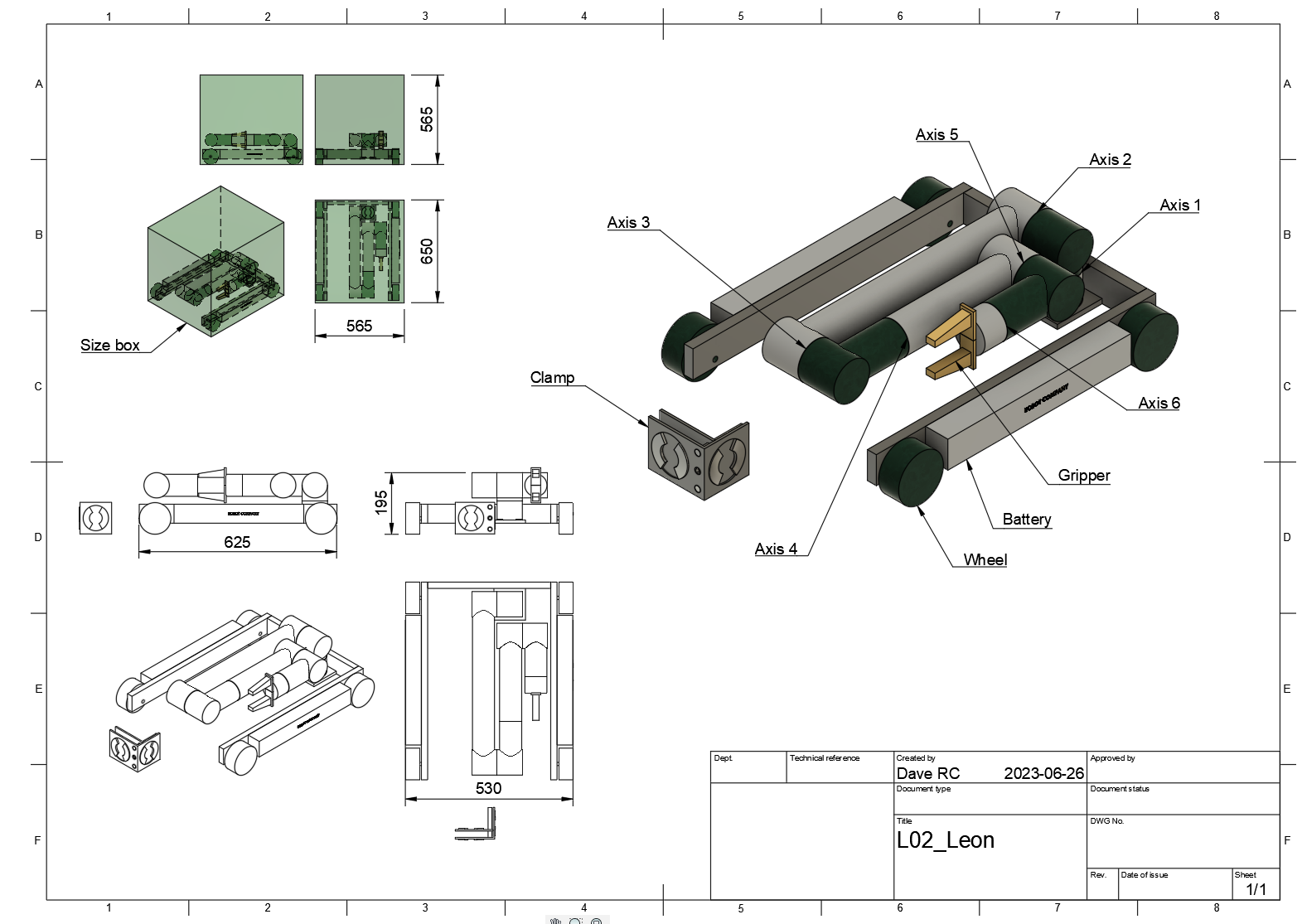
I also managed to fix the axis problem on the big arm as mentioned in the previous post. The arm now sits higher on the base. Where and how the arm is to be mounted will need to be workshopped later.
This will do for now. Hope it's entertaining.
The source files:
Next Post: