While ya’ll be making dogs, I’m making a lobster.
Post 3
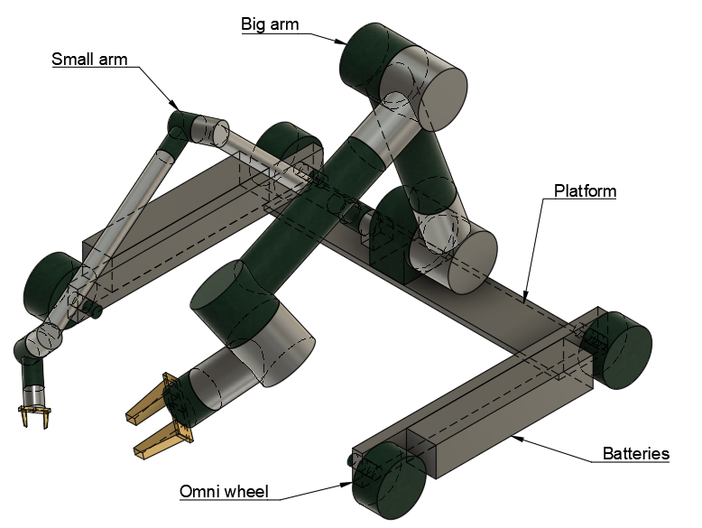
It's a set of two different-sized, 6-axis arms on a low-profile base that can move about with Omni wheels
The central application is small tasks in a light industry environment.
The designs here are all conceptual works. There are clearly issues to be ironed out at this early stage. See if you can spot the biggest problems before scrolling down.
Working title: “Leon”
Named after none other than the legendary Leon the Lobster.
Lobsters being one of the few animals with bilateral asymmetrical appendages. They have a different specialized claw on each side
Scribble
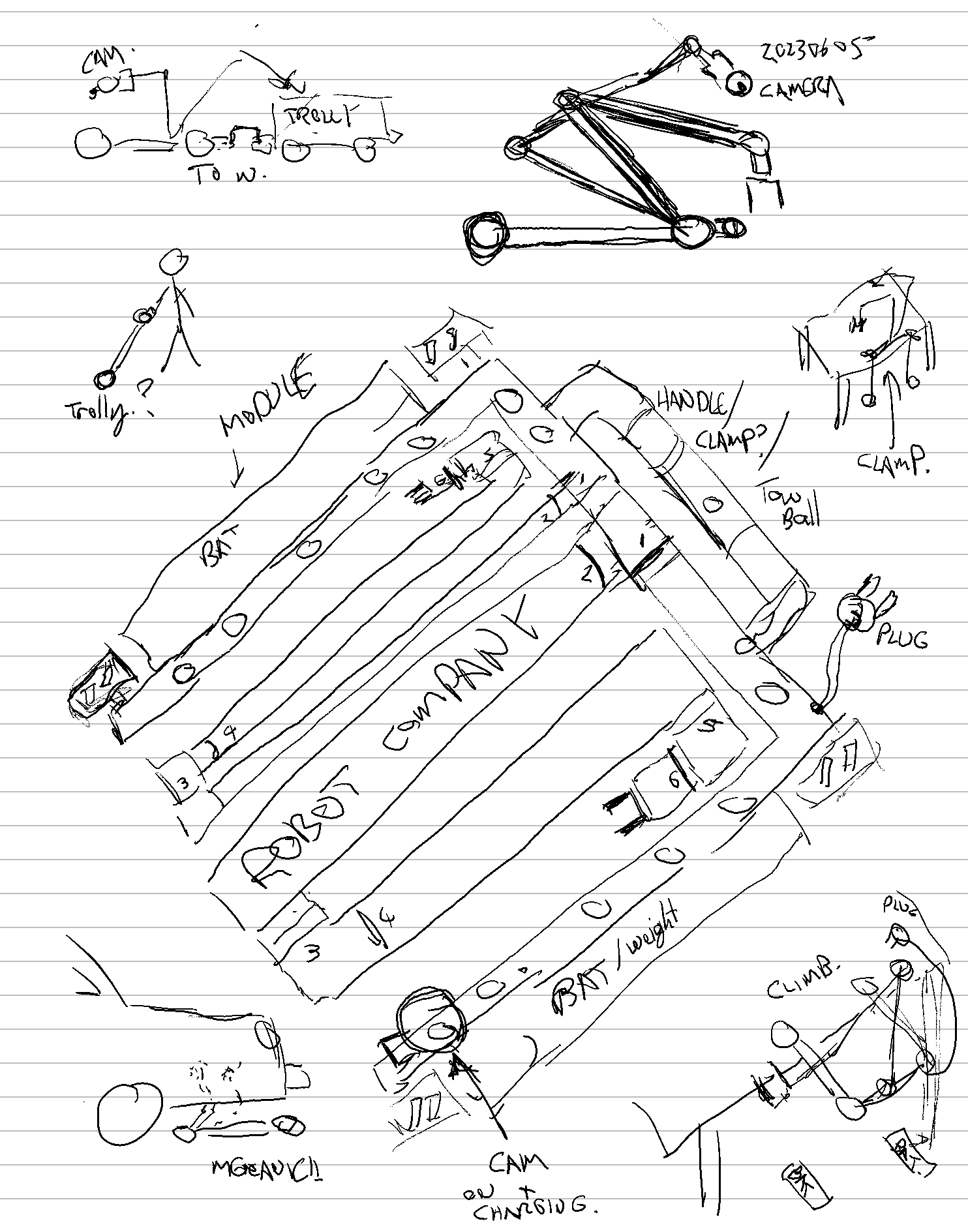
Here is some early sketch work on my reMarkable.
Some functions
There are a few applications scattered around the sketch:
- Pulling around a trolley of parts and extra tools.
- Mount points for expansion of functionality.
- The ability to remove/replace its own batteries.
- A flat design to fit under cars.
- Some ways to lift itself up to a table.
- A standard wall plug.
The concept here is that it's a mobile arm, but not really for all-day warehouse logistics. Its battery life should be enough to get it to its next workstation, where it would then plug itself in.
What is it good for?
It's a helper bot.
The main purpose is to be a tool that is less work to configure than it is to do the same job yourself.
Tasks like, “Hold this part and screw these bolts into it”, “Go and organize the items on that table.” etc.
The “what, why and how” of this is to be discussed in future posts (and linked here).
Its main areas of application are to be offices and light industrial environments.
It might still have value in the following areas, but these are not the central focus of this design.
- a high-performance machine for constant industrial use.
- a toy
- an educational tool
- a research robot
- for outdoor use like rugged terrains
- To be better or faster than a human, at anything.
If you want to go faster and better. Your local cobot supplier is the way to go. I recently talked with a couple of them at a Universal Robots convention. More on that later.
Some quick CAD work
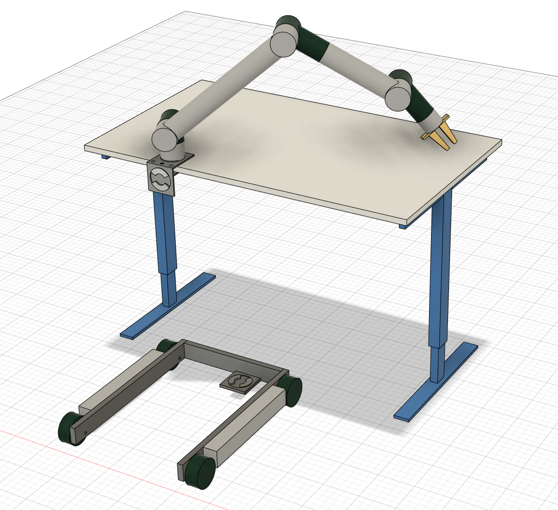
Here is the first stage mockup on Fusion 360.
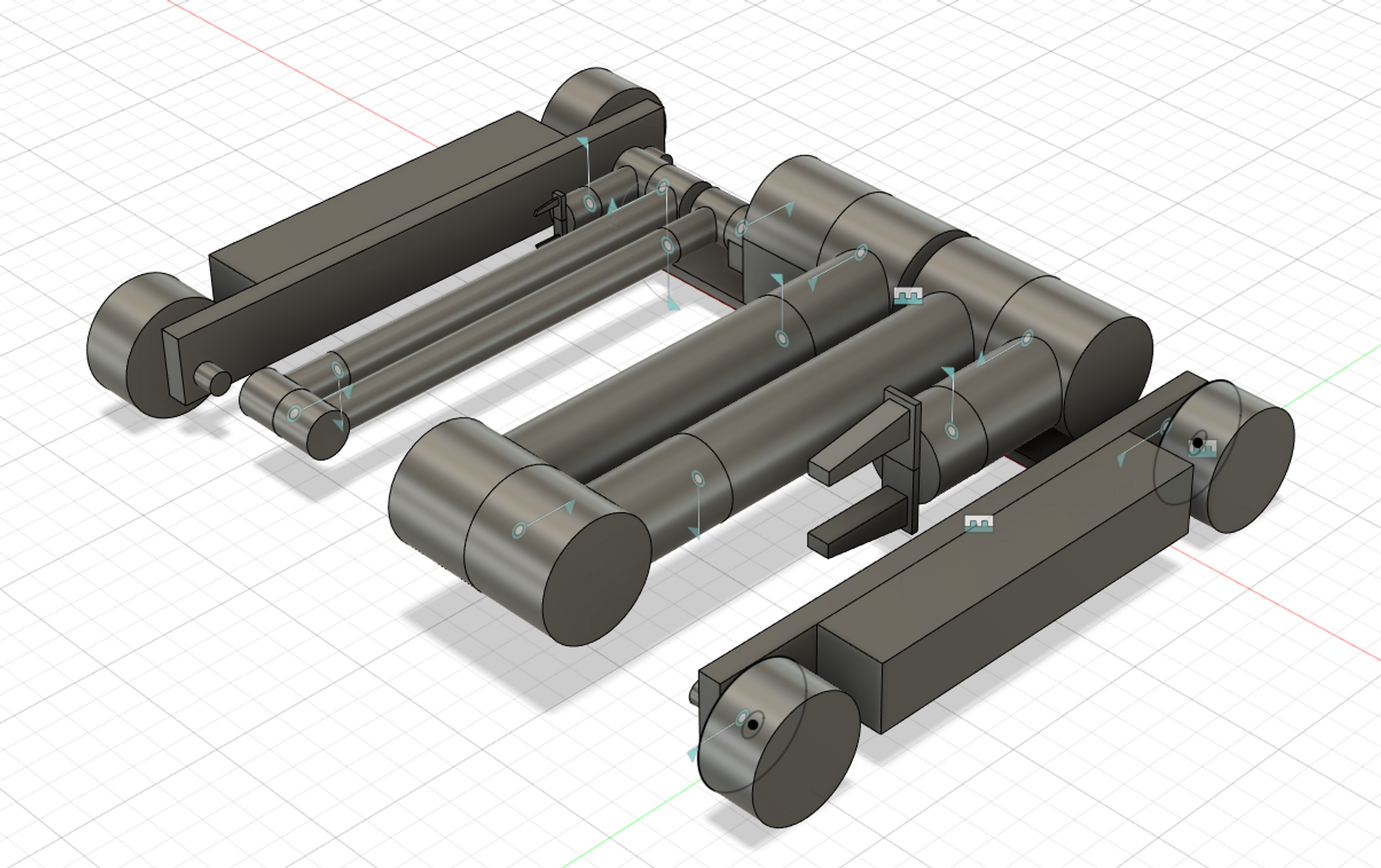
This was about 3 hours of work. CAD is not my strong point (by degree and career, I'm an electrical engineer) so I had to learn Fusion 360 from scratch.
This is a great tutorial: https://youtu.be/d3qGQ2utl2A
At the studio, we (someone else) use Solidworks for all our CAD needs. It's also great. But I wanted to try Fusion for the time being.
How big is it?
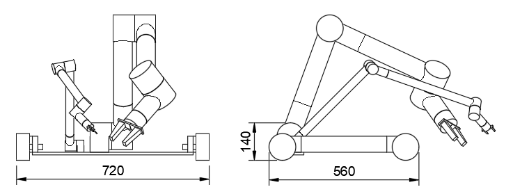
I made a few pieces of common Ikea furniture in order to get some idea of scale, reachability and store-ability. Here, I determined a good “size” for an office robot should fit the area of 565 x 565 x 650mm.
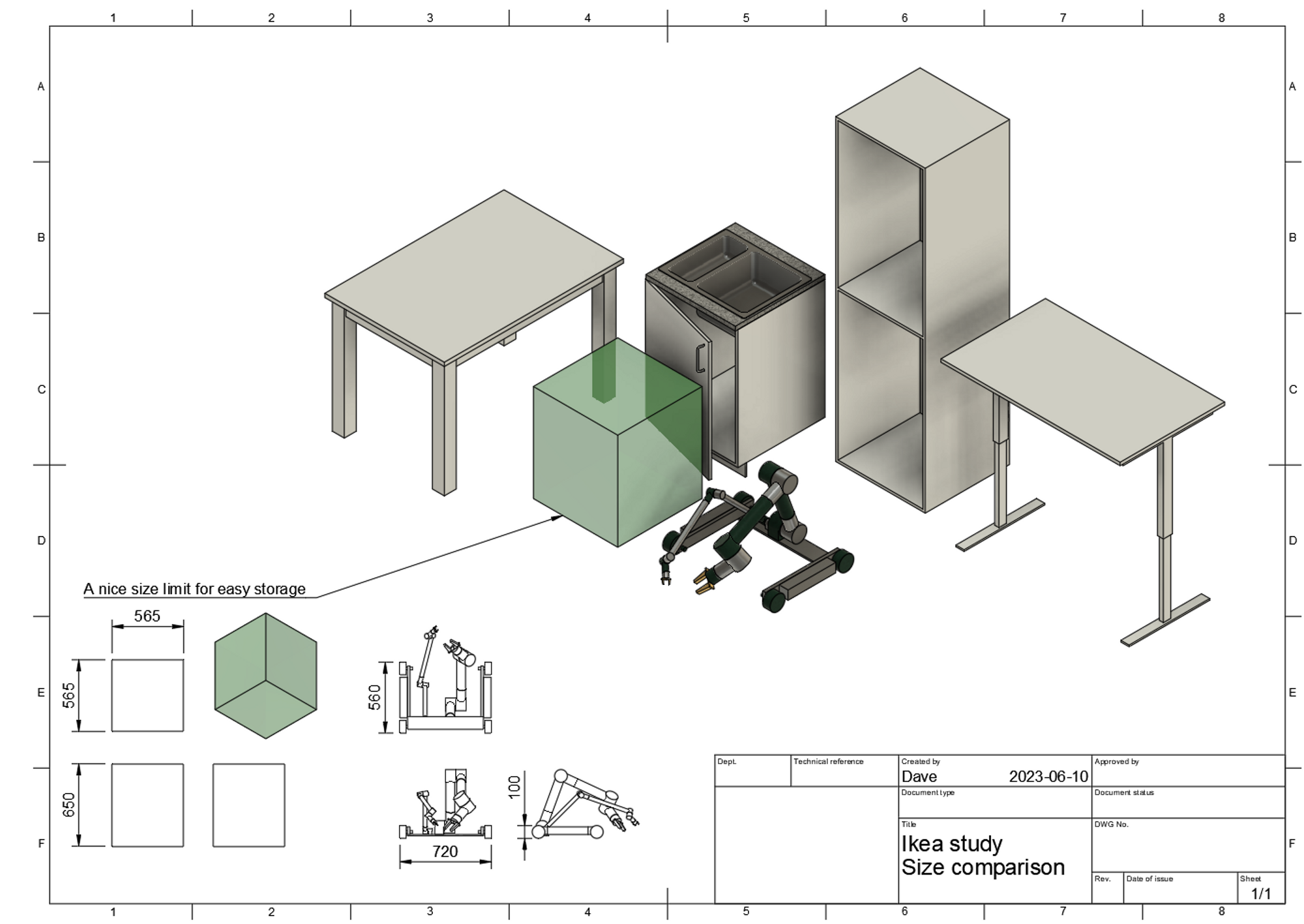
After putting the robot into the room, I found it to be too big be easy to store. 🤦♂
And it's defiantly too low to do the dishes.
Issues:
Terrible range:
Don't get too creative and optimize too early.
In the very first sketch I did, I had the 1st and 2nd axis flipped around.
This is not how 6-axis arms are typically designed.
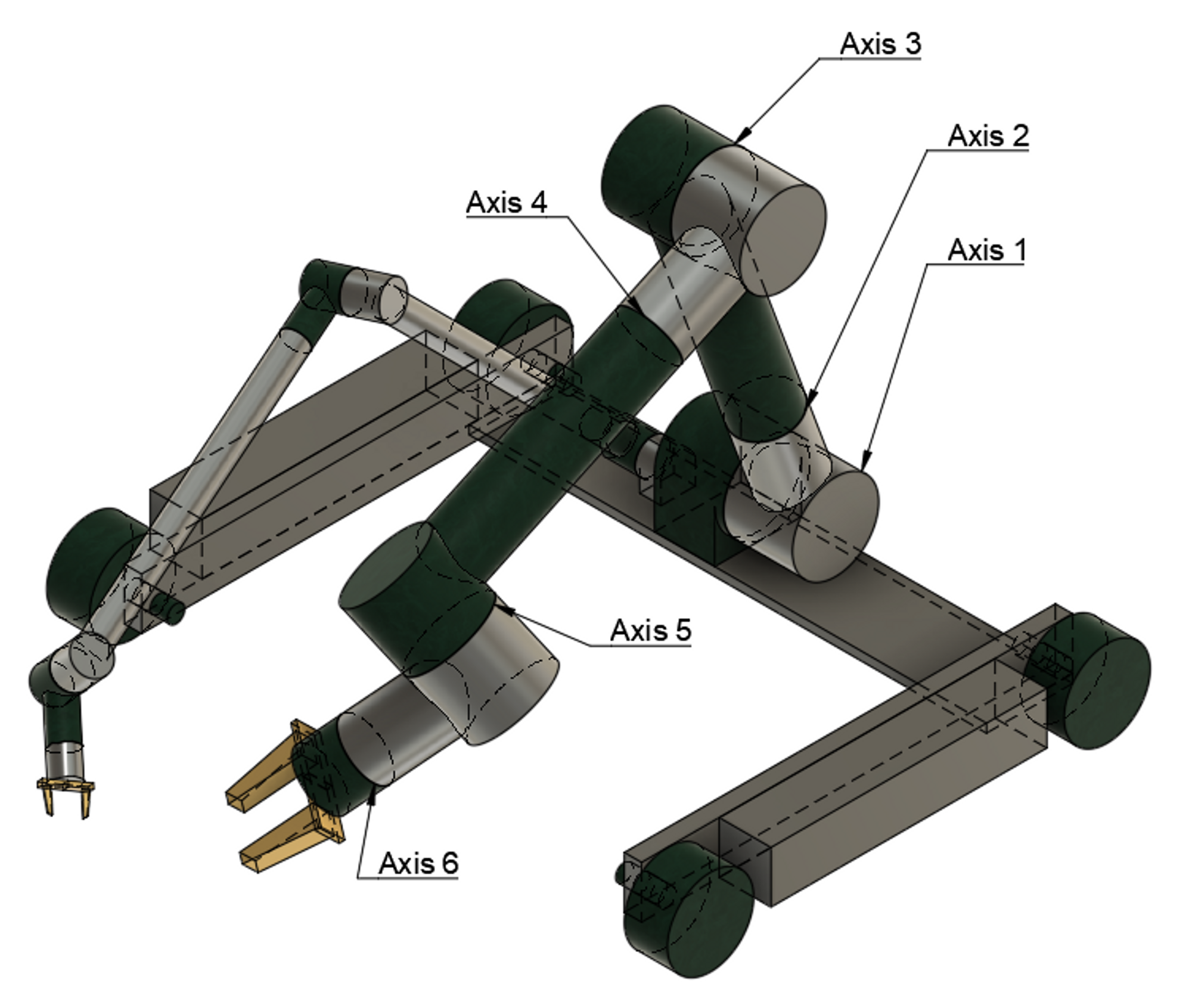
This is how a 6-axis arm should be designed.
Nonetheless, it doesn't take long to mock it up with all the joints to see why the design is flawed.
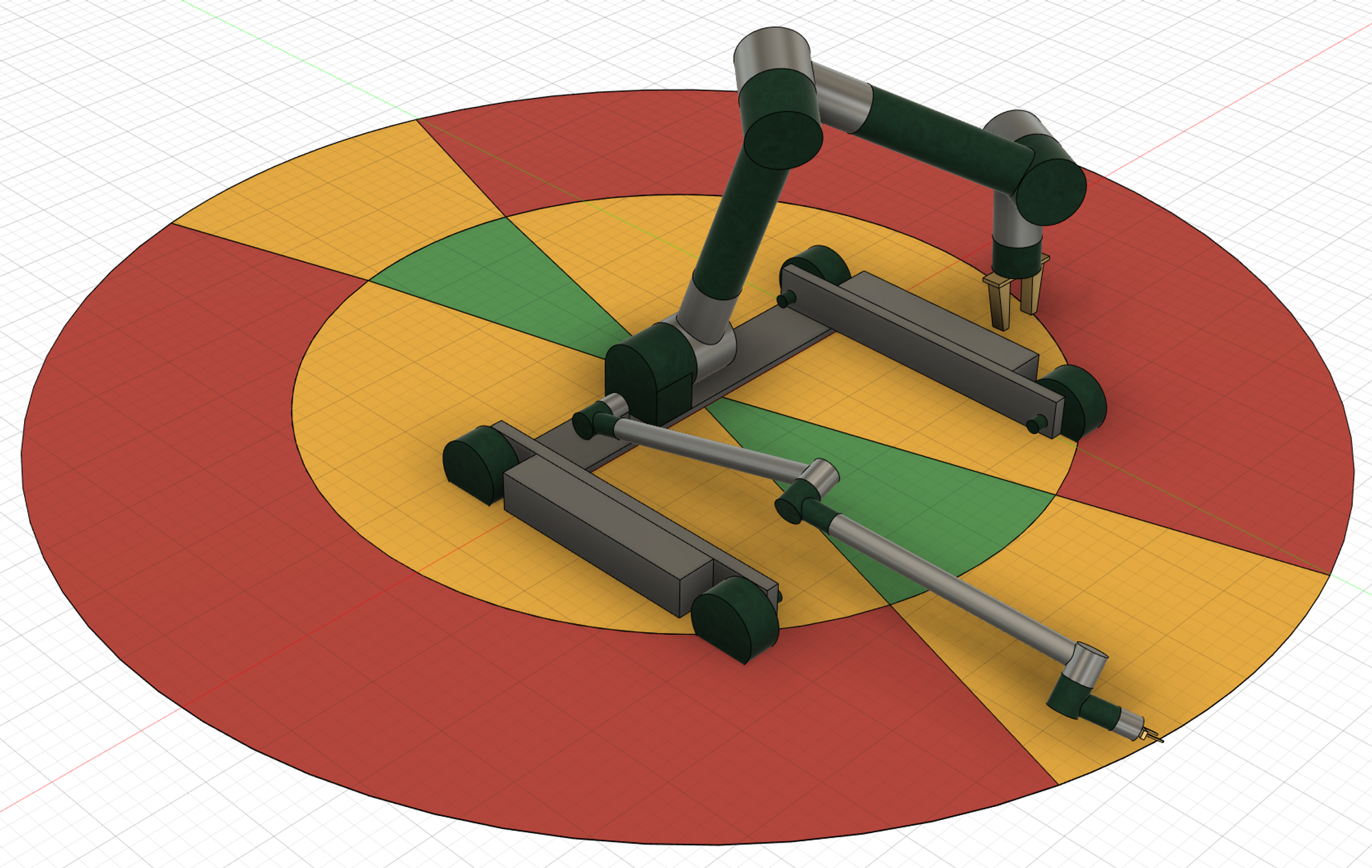
Green = can grip in most angles in this area
Yellow = can grab things, but only at limited angles
Red = cannot reach at all.
The first axis forces the entire upper arm to stay in line with the center of the platform.
The reasoning was some vague idea of part-reuse since the upper arm and lower arm would be somewhat the same. Another advantage is that it might make the total design pack-down flatter, giving advantages in transport and storage.
The thought was
Why make the first joint on the z-axis (up), when you can just move around on the omni wheels?
Yes, you can do that... but this is now the rough range of dexterity relative to the platform.
Basically,
- the working area is very limited and a lot of rolling around is needed to compensate for that.
- Using both arms together means they also need to be close to each other so that they can both be in the green area
- Any application on the platform itself gets greatly limited.
This is premature optimization at its worst.
Another important note: Axis 1 now needs to work harder because the weight of the motor on Axis 2 pulls on it. Here is Jeremy Fielding explaining the issues with moving heavy motors high up in the assembly.
Not a lot of room on the platform.
Clearly, the wheels are missing their motors, there are missing parts everywhere.
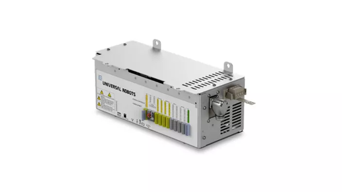
Robot arms are far from self-contained. The control unit, Motor drivers, and power supplies are not to be taken for granted. So when you hear “128mm” footprint… that’s not the total footprint.
The UR3e, for example, has an external control box called "OEM control box" that’s about 5kg and the footprint of a computer keyboard. But those are probably great specs for the performance and reliability that they are known for.
So there will probably be some compromises in order to get things to really fit. But I am confident of finding a way forward here. For example, here is a very compact design with a lot of features.
What? Is it just going to crawl around on the floor then?
yeah, I know right? Clearly some changes are needed.
Have you thought about the ground environment where it’s likely to operate?
Perhaps some adaptable ground clearance of sorts?
Otherwise, the environment will need to be really flat and you will have issues with door thresholds.
-DW, a friend
To be continued…. here
Speaking of…
What’s with the dog reference?
A lot of dog robots getting made these days. … most of them just trotting around with cameras on them.
Perhaps a discussion for another time.
Finally: Can I get the source files?
Next Post: