A simple reversing gearbox using planetary gear sets
Post 11
This is the 2nd article in a series on mechanics. It is an extension on A few notes on planetary gear sets. Nothing new or novel is being shown here. This is an educational post and a building block for future work.
The gearbox
This is a basic forward/reverse gearbox. It's about as simple as it gets.
One can do much more than this with just two planetary gear sets.
This set is simpler than other designs as it has no clutches or meshing requirements. Of course, those parts do exist for good reasons in many applications.
The design decisions here are all for demonstrating the principles of how it works, rather for any practical application. Hopefully it is easy enough to understand.
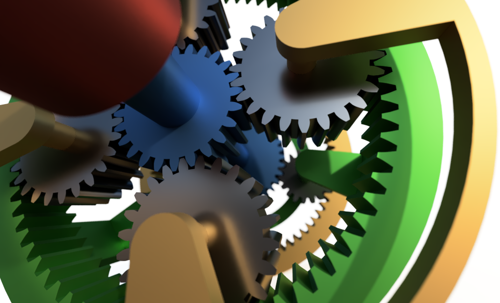
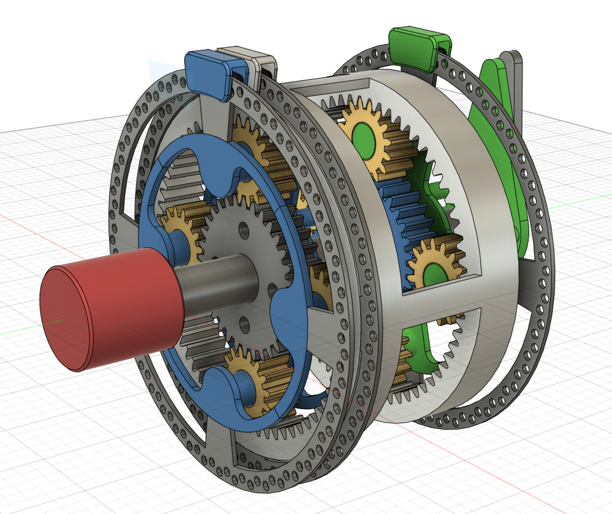
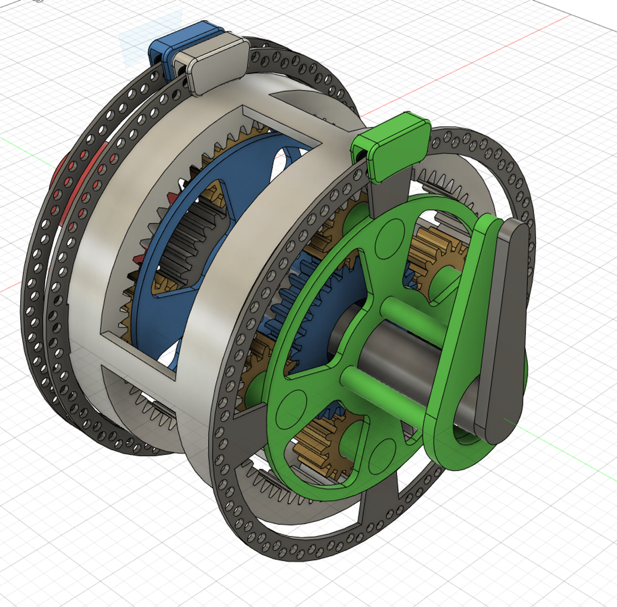
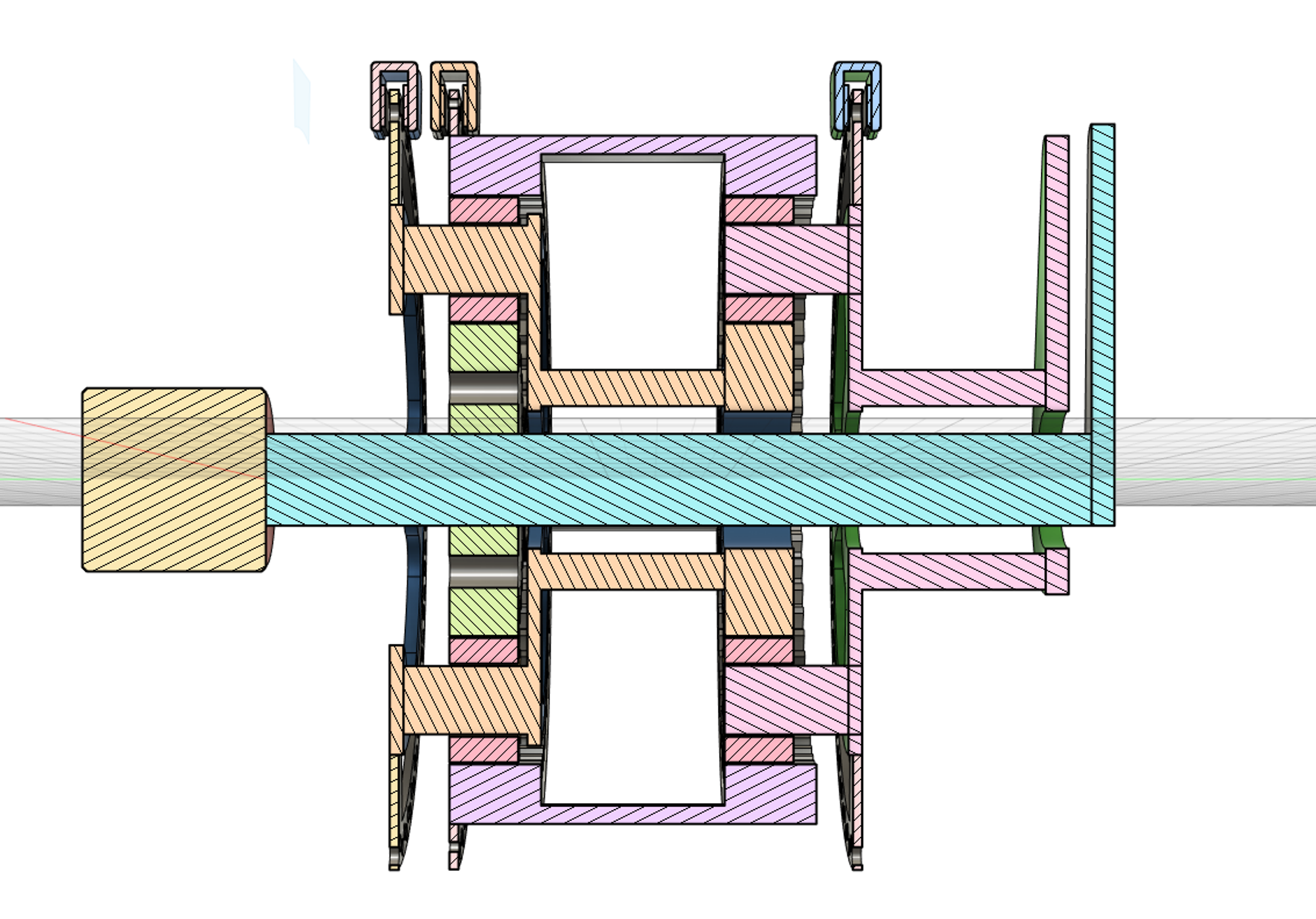
It looks like this.
The operation modes are:
- Forward at 1/3rd input speed.
- Reverse at 1/3rd input speed.
- Stop while the input may still rotate.
- Neutral: where input and output is free to move independently.
- Locked: where nothing is free to move
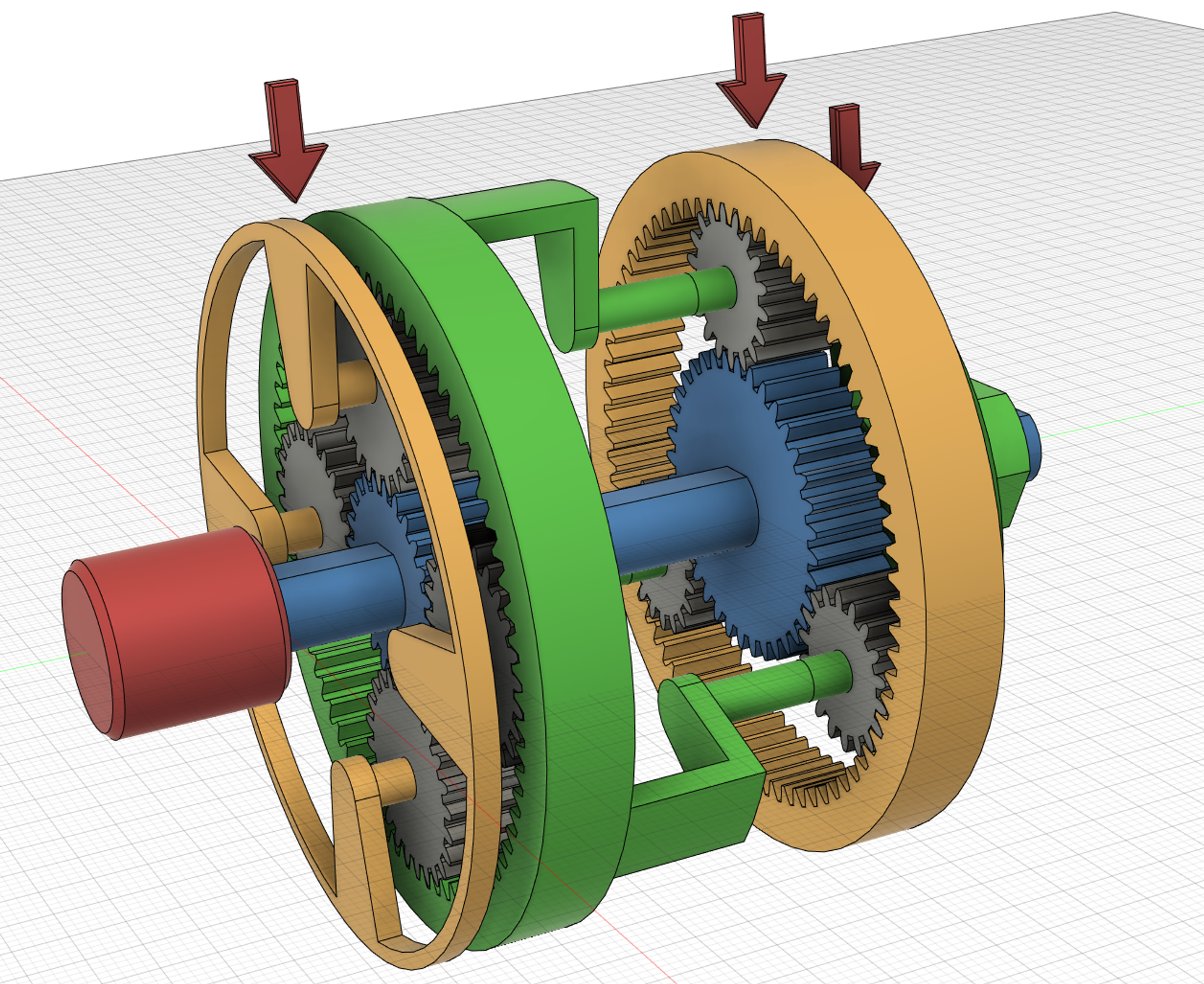
There is one motor (in red) driving an input shaft (in blue)
There are 2 planetary gear sets that connect the input shaft to the output. Finally, the output shaft (in green) is at the opposite end.
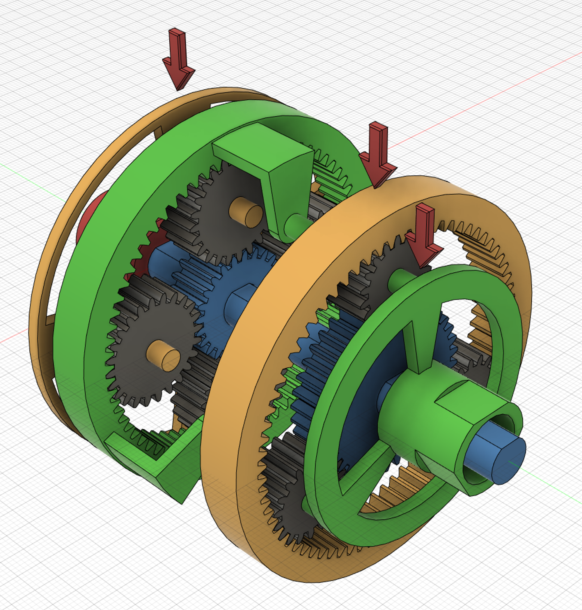
The 3 red arrows show where one would apply a break to the system in order to apply one of the modes.
The input (blue) is passed all the way through the output (green) so that we can see most the functionality from just one camera angle.
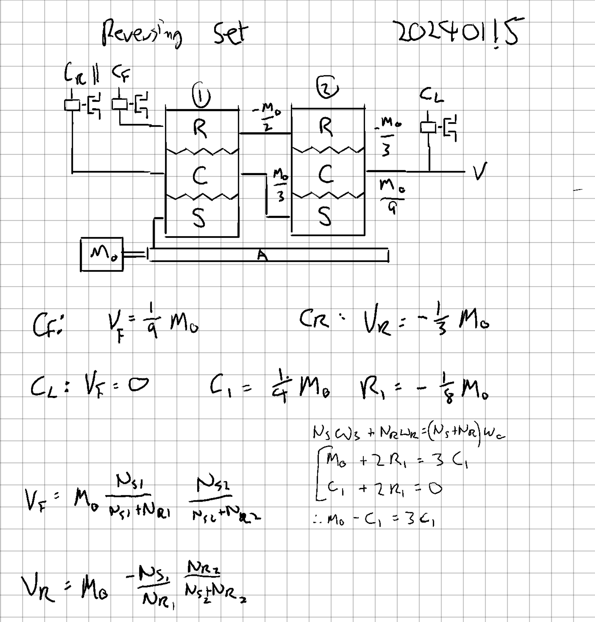
Here is a schematic for the design.

You can see that the schematic is based on a cross-sectional look the of the 3d model.

Now lets look at the modes of operation.
They are 20mg each, and it might take some time to load them. Let me know if it seems like something is missing.
Forward mode
In forward gear we apply the forward brake. This locks the ring on the 2nd gear set

The 2nd gear set is now in a Fixed Ring mode.
This gear set has a 1+2=3 ratio. (as we explored in the last post)
It means that the carrier (output) will follow the sun (input) at 1/3rd of the speed.
The 1st gear set does not affect the system. It is in Neutral mode. The sun is moving at the input speed and the ring is moving at the output speed. From the perspective of this gear set, the sun and ring both become inputs which drive the carrier. The carrier will move at 1/2 of the input speed, but it's not connected to anything, so its speed is not relevant to this mode.
Reverse mode
To achieve reverse, we select the reverse brake instead of the forward brake.
This puts the first gear set into Fixed carrier mode. The ratios we use here are 1+3=4 (rather than 1+2=3 as in previous examples). Now the output moves at -1/3rd of the input speed

The 2nd gear set is now in Neutral mode mode and will have no effect. As before, the ring will find a speed that is driven by both the sun and carrier. Again, this speed is not very important because it doesn't go anywhere.
Stop mode
For stop mode, we simply hold the output fixed using it's brake.
In this case, both gearsets are now in Neutral mode.
The input may still turn, but now the motion is only transferred to the free spinning parts: the 1st carrier and 2nd ring. Their speeds become 1/4 and -1/2 respectively.

The result is that the input can rotate freely while the output is fixed.
Neutral mode
Neutral mode works the same as stopped mode. Except no brakes are engaged and the output is free to move.
There are an infinite number of speeds one could demonstrate here. Let's just look at output is 1/3 and input is fixed.

Again, we see that all the motion goes to the freely moving parts.

Of course, this is not a perfect neutral. Any friction in the gears will transmit some of the power between input and output. This would make it a bad choice for anything with a very low idle load on the output. Like a propeller on a boat for example.
This is where clutches inevitably become a good idea. It depends on your application.
Locked mode
Activating any 2 brakes will result in all parts, including the input to be stopped. This is because any combination of 2 brakes will cause on of the gear sets to become locked to zero speed.

It should also be pretty intuitive that you can't drive and stop something at the same time, or go forward and reverse at the same time. Nonetheless, this mode needs a name. That and we get to use magenta for something.
Changing gears (modes)
Exactly what happens when you change between gears is beyond this basic intro. Things like momentum and friction need to be considered based on your application.
Like most gearboxes, one typically needs to go via neutral in order to change gears. This includes going to and from the stop mode.
This is fine if your project plays nicely with momentum: like a car.
But it’s not great if you work with precision: like a robot arm or a crane.
One might imagine changing from forward to stop as quickly as possible. In reality momentum of all the parts will be challenging. This will also be some effects back on the input. The simple way to keep precision is to bring the input to a stop. Then go via Locked mode to change gears. Otherwise, you need to add more complex parts like clutches, torque converters and/or control systems.
What is it good for?
On its own. Probably not much. It's just a conceptual model. Especially if you have an electric motor can reverse itself.
But, I do have an application in mind where this is a small part of a larger solution. So I put this post together to reference back to.
Making the animations.
This section is about CADing up and animating the parts in Fusion 360.
The end goal was to create a looped animated GIF where all the important parts are visible. It should be easy to understand.

There is no “physics” in this software, so all the rotations needed to be calculated. (rather than to have a physics engine let the gears push each other around). While fusion 360 has joints motion links, these are (frustratingly) not available in the animation tool so all of the movement needs to be done manually.
This is the full table.
| Gear | Teeth | Ratio | Forward | Reverse | Stop | Neutral | |
|---|---|---|---|---|---|---|---|
| Input | Sun 1 | 24 | 1 | 1 | 1 | 1 | 0 |
| Output | Ring 1 | 72 | 3 | 1/3 | -1/3 | 0 | 1/3 |
| Planets 1 | 24 | 1 | 0 | -1 | -1/2 | 1/2 | |
| Carrier 1 | 96(4)* | 4 | 1/2 | Brake | 1/4 | 1/4 | |
| Input | Sun 2 | 36 | 1 | 1 | 1 | 1 | 0 |
| Ring 2 | 72 | 2 | Brake | -1 | -1/2 | 2/3 | |
| Planets 2 | 18 | 0.5 | -1 | -3 | -2 | 1 | |
| Output | Carrier 2 | 108(3)* | 3 | 1/3 | -1/3 | Brake | 1/3 |
Table 1: the relative speeds of all parts for each operational mode.
It would take lot of extra work to go into detail on the math. You either love math and can do it yourself, or you’re not interested at all and won’t read it.
Overall, the process was:
- Fill out all of the input and output speeds. Including the brake settings for each mode.
- Apply the equations below from Wikipedia to complete the rest of the table
- Find a set of gear teeth that will both work and animate nicely.
Here are the equations.
$$ N_s w_s+N_r w_r=(N_s+N_r)w_c\\ N_sw_s+N_pw_p-(N_s+N_p)w_c=0\\ N_rw_r-N_pw_p-(N_r-N_p)w_c=0\\ $$
This simulator is a good way to find some nice teeth counts to satisfy the gear ratios. One thing to keep in mind is the goal to make a short looping GIF animation. Each gear needed a number of teeth that would work with the fractions in the table.
i.e.: if ring 1 had 64 teeth. After a 1/3rd rotation, it would have moved 21.333 teeth. The animation would loop here and would glitch. With 72 teeth, it moves 24 whole teeth and there will be no jump in the animation.
*. For Carriers, this is the “effective” number of teeth. In brackets are the number of planets on the carrier. This also needed to be selected to achieve a loop-able animation and is the only reason why set 1 has 4 planets and set 2 has 3 planets.
Earlier works.
The design we looked at today has some flexibility in terms of its gear ratios. Here, forward and reverse are matched. But you can also tweak these to get some unmatched values.
Before this design, I had a model that did 1/9 forward and -1/3 reverse. It also featured some nice disk brakes as well. I later dropped these in favour of the red arrows. Disk brakes added too much of a production look and made it more difficult to focus on what is happening.
License
All the images on this page with CC0 are in the public domain and can be found on Wikimedia Commons.
I didn’t bother with all of the images because some of them probably are not as useful. Feel free to contact me if you want me to upload a CC0 version of something. It probably won't be an issue.
Next
Next will likely be a look at worms.
This article ends abruptly.